construction line inventor drawing
Freedom of Information Law FOIL Pedestrian. Projects in Your Neighborhood.

Perpendicular Angle Dimension In Drawings To Avoid Creating Sketches Autodesk Community
Specify a second point through which the construction line should pass.
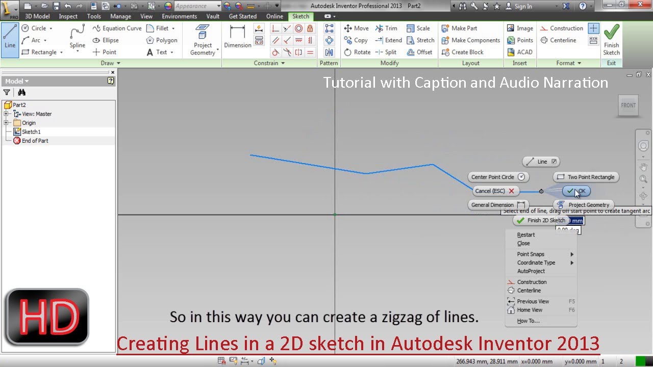
. Similarly continue specifying the angle end point to draw multiple lines. You now have these sketches visible. Now it will ask you to specify the point from.
The tool is designed for CAD style drawings but works just as well with any other type of. He is currently a Design Technology Consultant in Tulsa OK. The regular AutoCAD construction line functionality is still available via the XLINE command.
Drawings for interior design projects generally use three line widths. Purchase Autodesk Inventor from the Redstack online store today or learn more about Autodesk Inventor training course. Rotation handles are available on three direction axes of the 3D Orthogonal Route tool.
He also serves as Vice President on the AUGI Board of Directors and is a member of numerous Autodesk user panels. You can define a specific angle value then place your construction line in drawing scheme by clicking. Available on the Autodesk App Store ConstructionLines is an app that helps you create a construction line of infinite length and gives you the ability to select Xrefs and blocks too.
An easy way to include lines and curves in the drawing is. Start a sketch. Construction Lines is a tool for accurate CAD style modelling.
Draw your line at roughly the right lengthangle. Project the Y axis into your sketch this varies depending on what your sketch plane is. Take a look at ConstructionLines on the Autodesk App store and its free Check out the entire series for more AutoCAD apps available on the Autodesk App Store.
You could do the same thing with workplanes andor axes. Build snappable guide points and guide edges draw lines and primitive shapes in place automatically create faces in closed geometry and precisely move object geometry around a scene. AutoCAD Construction Line with What is AutoCAD Installation Versions Download AutoCAD 2020 Free Trial AutoCAD 2019 AutoCAD 2018 AutoCAD vs AutoCAD LT 360 Icons etc.
Insert a new Geometric Set for the geometry you want to show on the drawing and then move the construction lines curves sketches points into this Geometric Set. Machine operators production line workers and. Guide edges and points allow for a construction workflow.
Specify a point to define the root of the construction line. Build snappable guide points and edges draw lines and primitive shapes in place automatically create faces in closed geometry precisely move duplicate and rotate geometry around a scene and cut-through meshes with extrude. Construction Lines is a tool for accurate CAD style modelling.
Optionally right-click in the graphics window and then determine the Auto-Dimension option depending on whether it needs. To learn more about the full range of products training and support. You can create your construction line by defining angle of vertex.
You can find the construction line command from the Draw menu of the Home tab of this software with this type of line icon. If you are in progress of creating the next route point right-click and select Done to quite the Route command. In the Model browser or graphics window right-click a sketched route point in the parametric region and select Draw Construction Line.
These lines will be drawn with a fixed specified vertex point. Frank has worked in various design and CAD Management roles with AutoCAD and Autodesk software since 1986 v262. Or you can use short cut command for the construction line which is type XL then press enter button of the keyboard and your command will be active.
No command line entry is required. Press Enter from your keyboard to create your construction line in Autocad. Dimension it click Dimension click the line and then hover the mouse around until the ordinate icon shows up and you can dimension the length of this line add the angle.
Thick dark medium and thin light. Production drawings 1 2 3 sometimes called working drawings are complete sets of drawings that detail the manufacturing and assembly of products as distinct from engineering drawings prepared by andor for product engineers whose task is to decide how best to manufacture the products. Continue to specify construction lines as needed.
Hide all the other Geometric Sets so the CATPart looks like what you want to see in the drawing. Figure 3-7 These are common line types used in drawings to describe objects hidden conditions and important relationships between components and space. Answer 1 of 4.
The ends can also be adjusted after you close the properties. It is usually a line that is set to a NO PLOT layer so that you can draw all over and make changes without any of it actually making it into a final plot by accident. Create a Construction Line by Specifying Two Points.
This should work for most intersections. Construction lines can be created in an Autodesk Inventor design by sketching the line as you normally would and then select the construction line command. It is shown in the below image.
In this session you will learn How to draw Horizontal Vertical Angular Construction Lines. Click Home tab Draw panel Construction Line. Rotation handles are available on three direction.
However the AutoCAD Architecture 2023 toolset construction line feature is designed to give you a more intuitive way of drawing construction lines based on the geometry of existing objects or linework. You can create your construction line that is offset of a selected linear object. In the IV help index look for sketches in drawings for more info.
All subsequent xlines pass through the first point specified. If you are dimensioning to an intersection after placing the dimension open the properties dialog box and on the Display tab check the box for Enable intersection witness lines to show parametric witness lines. Make them a unconsumed sketch not part of the base sketch then in the IDW right click on the view select show content then on the part right click and select show sketches.
In the Model browser or graphics window right-click a sketched route point in the parametric region and select Draw Construction Line.
Imaginit Manufacturing Solutions Blog Autodesk Inventor

Solved Construction Lines Icon Missing Autodesk Community Inventor

Gridlines In Inventor 2017 Autodesk Inventor Users Grabcad Groups

Copy Sketch Geometry With Autodesk Inventor Tedcf Publishing

How To Make Ellipse Helical Autodesk Inventor Users Grabcad Groups
Mod The Machine Inventor
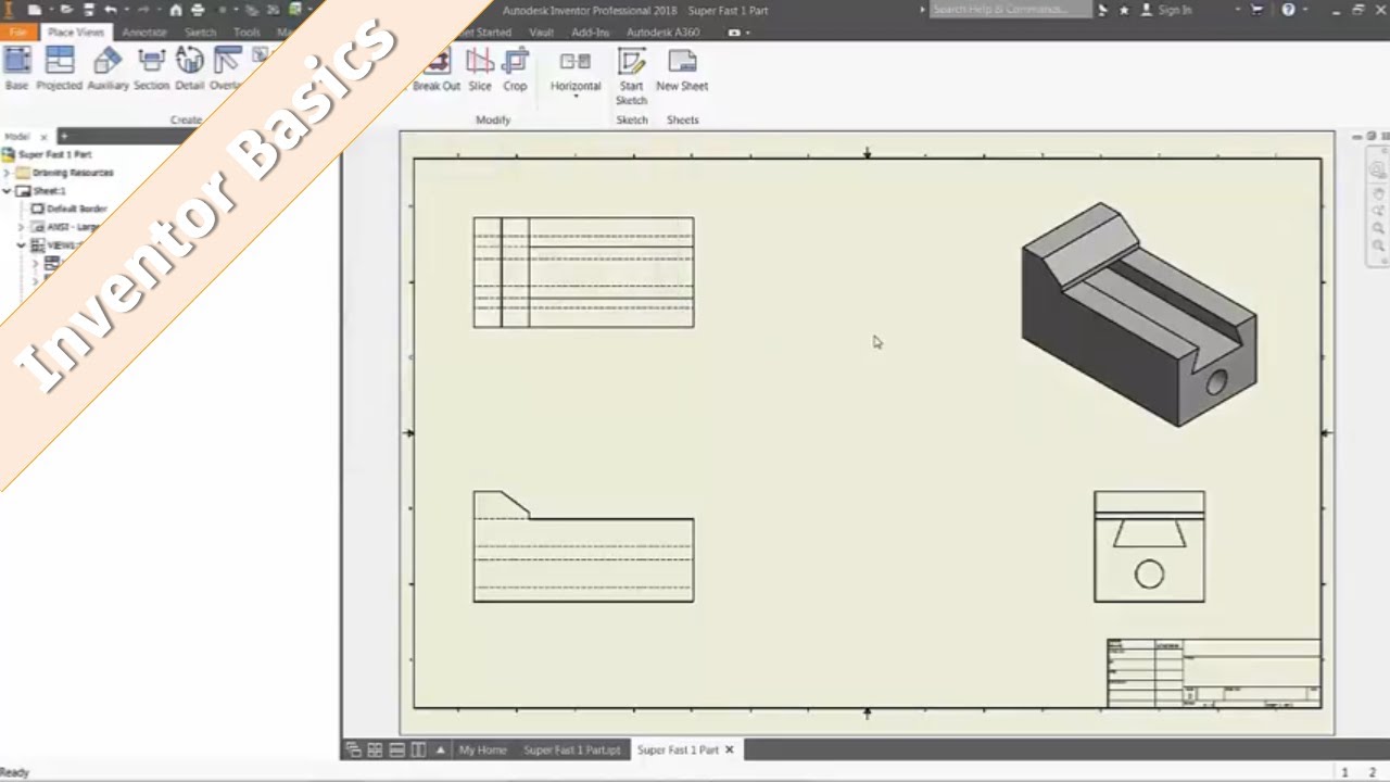
Inventor 101 Detail Part Drawings From 3d Cad Youtube
Inventor Tip Using Construction Lines Arcs And Circles To Sketch Geometry Ascent Blog

Controlling The Visibility Of Multiple Sketches On An Autodesk Inventor Drawing Inventor Tales

Solved Misconception Of Construction Line Type In Fusion 360 Autodesk Community Fusion 360

Solved Construction Lines On The Inventor Drawing Autodesk Community Inventor

Solved Construction Lines Icon Missing Autodesk Community Inventor

Inventor Tutorial Using Construction Lines Video 11 Youtube

Project Geometry As Construction Lines Inventor 2018 1 Youtube

5 Autodesk Inventor Tips In 5 Minutes
Creating Lines In A 2d Sketch Autodesk Inventor Youtube
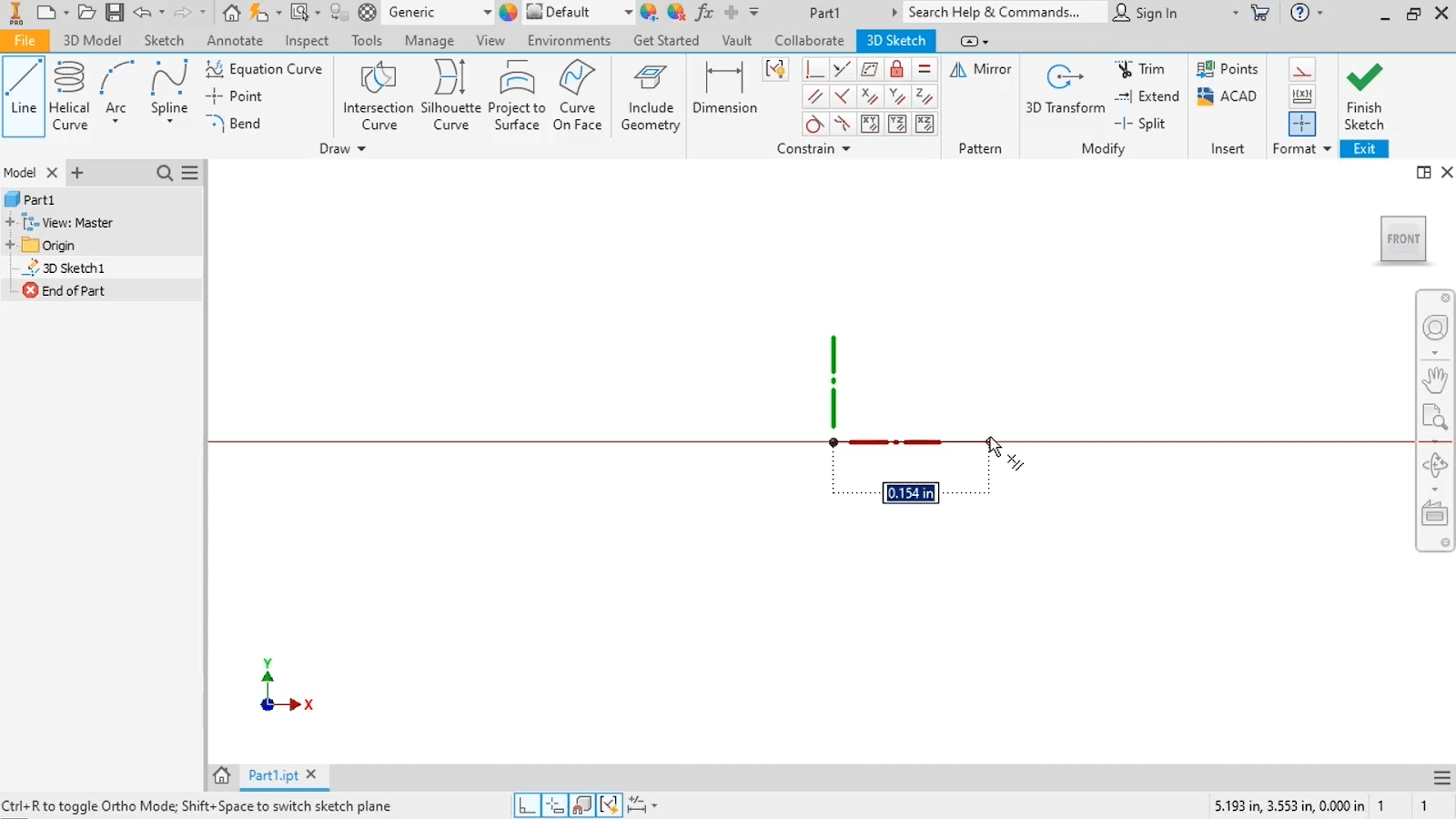
Autodesk Inventor Parts Tutorial Begin A 3d Sketch For Part Design
Sketch Object Properties Imaginit Manufacturing Solutions Blog
Linear Diameters Quicker Drawings And Model Modification Imaginit Manufacturing Solutions Blog